Hey Check Out My Bike
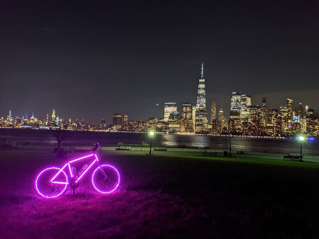
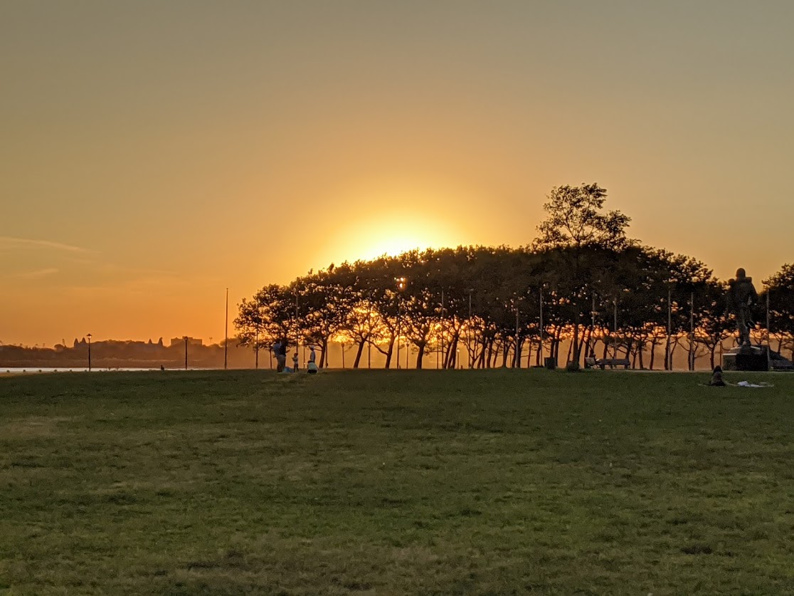
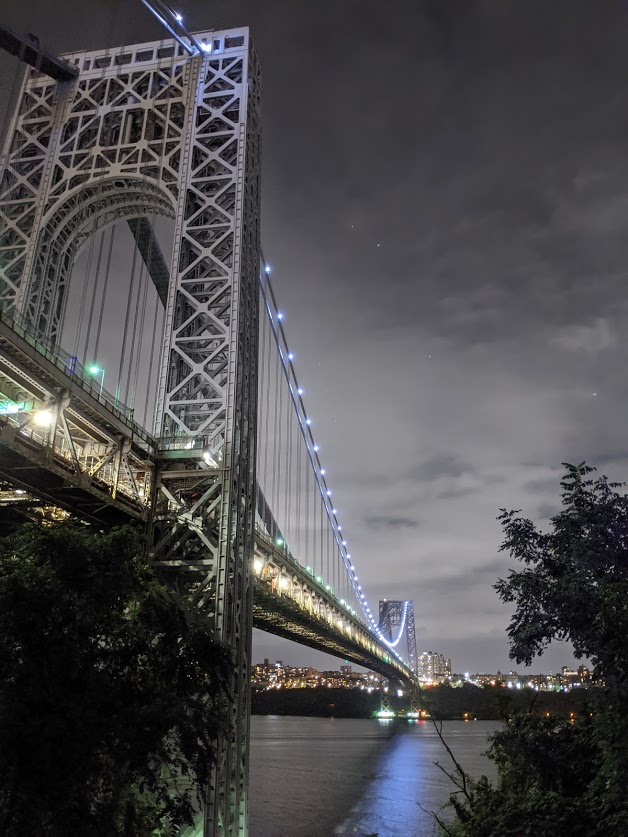
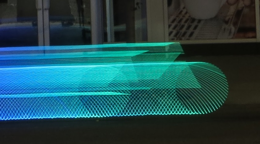
long-exposure photos:
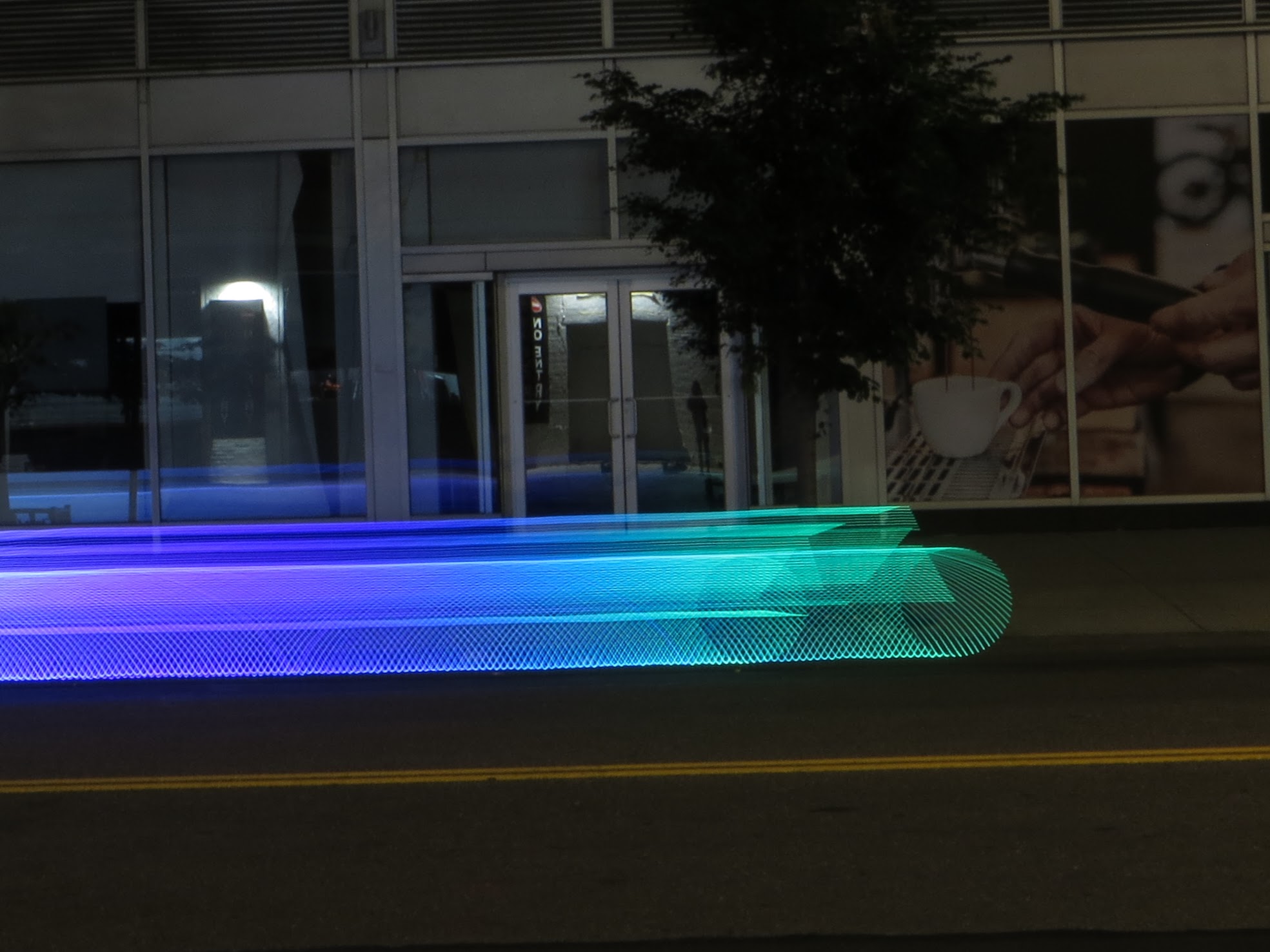
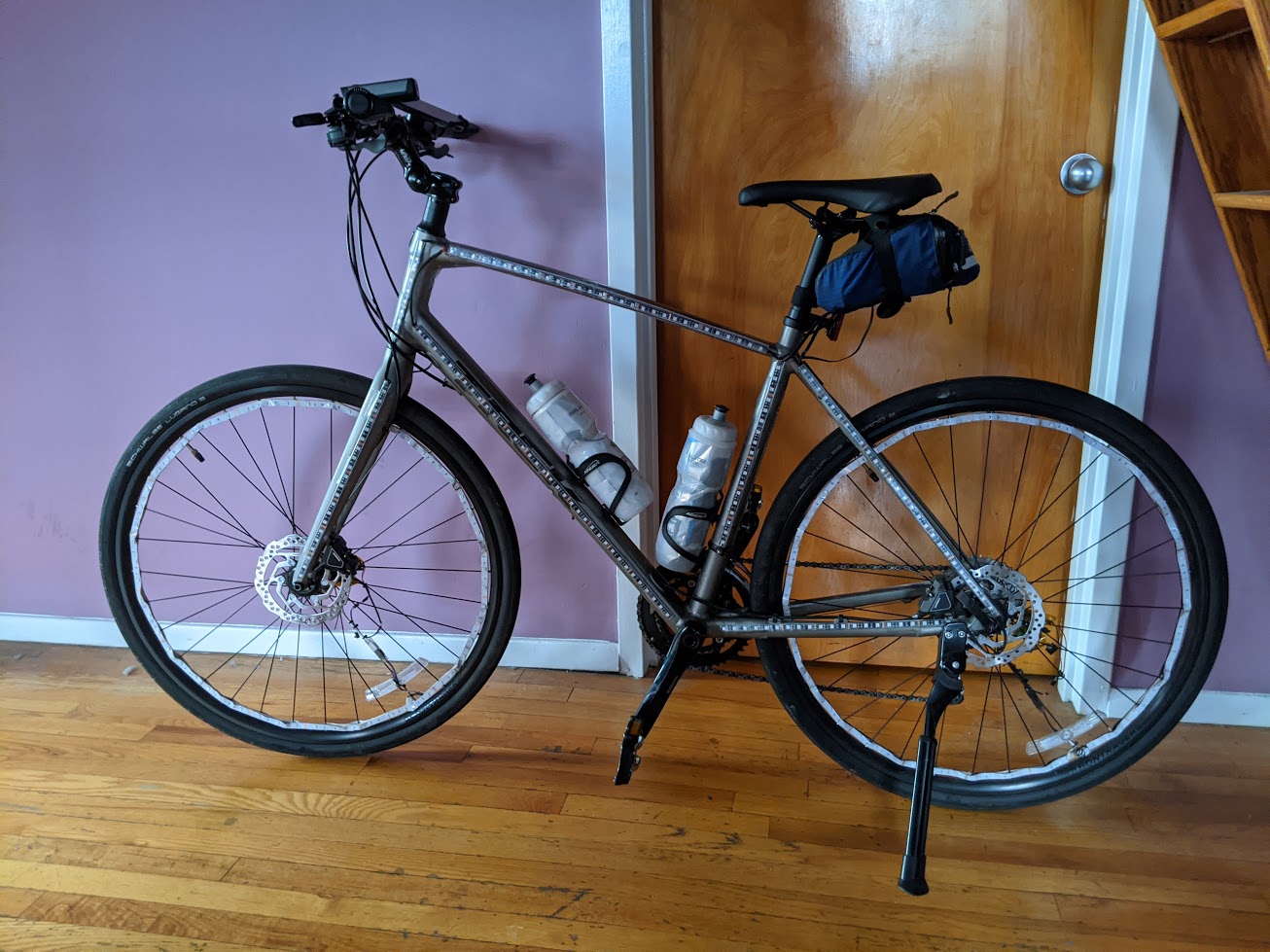
There is a bike club in Jersey City, NJ called BikeJC.org, and during nice weather they get together at night and bike around with lit up bikes.
I wanted to participate and jazz up my bike, and after several design iterations, I’m fairly happy with the result!
How It Works – High Level
There are computers controlling lighting circuitry. The trick was that I wanted was a whole-bike synchronized effect.
The biggest challenge was dealing with the fact that tires rotate, and so getting color signal to the tires was problematic if wired. Slip disks were considered, but ruled out as complicated/noisy/brittle.
So wireless was the way to go. But if wireless, how to synchronize?
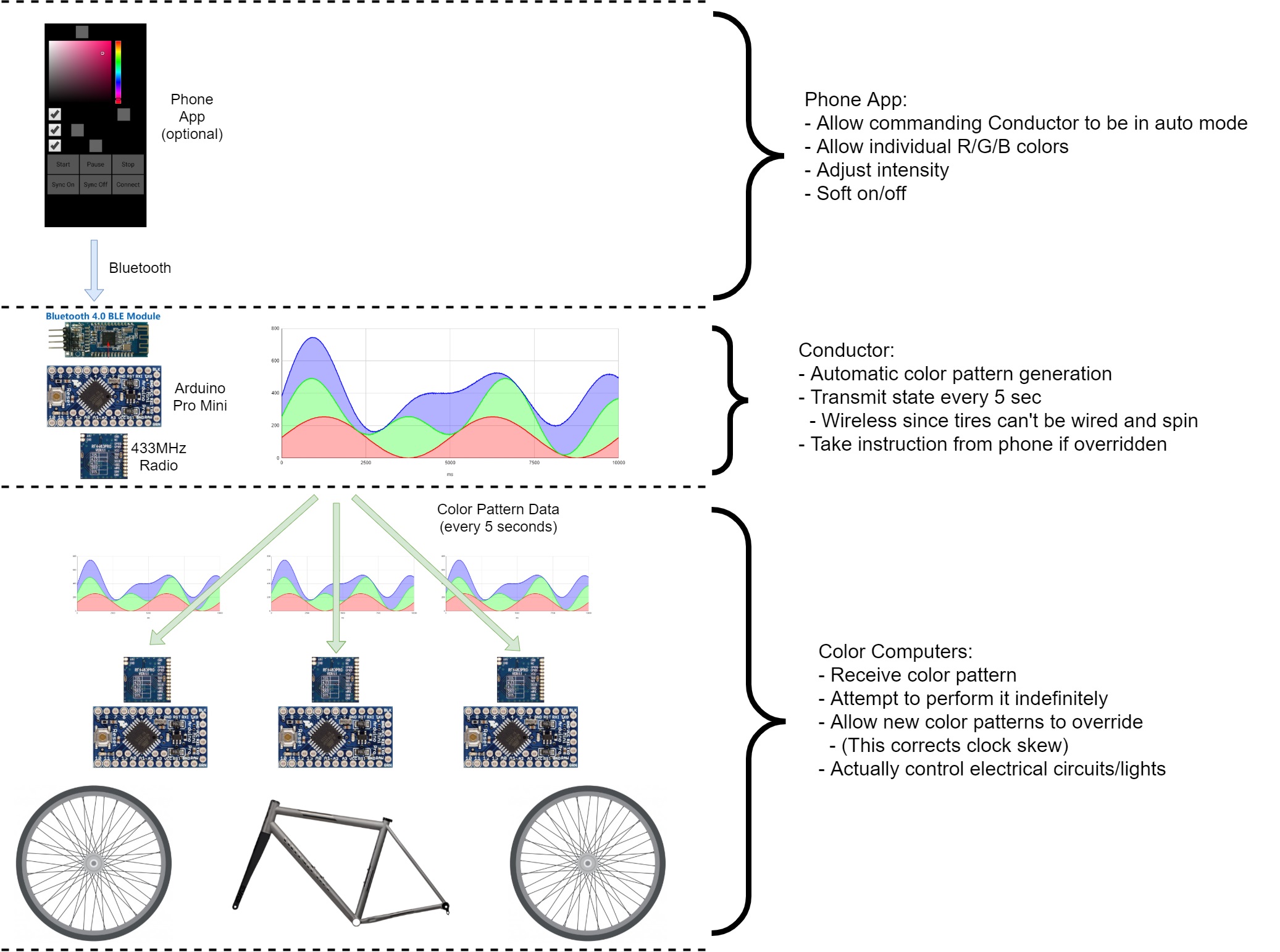
The super summary of the solution is:
- Have a single computer figure out a lighting pattern to follow over a period of time
- This is the Conductor, and it itself follows this pattern in real time
- Every 5 sec, Conductor wirelessly transmits the pattern, and current state of the pattern, to the receivers
- 3 computers receive it, correct their state, and follow the pattern
- This is the front tire, rear tire, and bicycle frame
The listener computers don’t know about each other, and don’t need to. Provided they follow the pattern and have reasonably accurate clock speeds, they’ll be in sync.
I made an app for the phone which can communicate with the Conductor to influence the pattern/state, which is then forwarded along.
Here’s a diagram:
More Details – Electrical
The Lights – Electrical Control
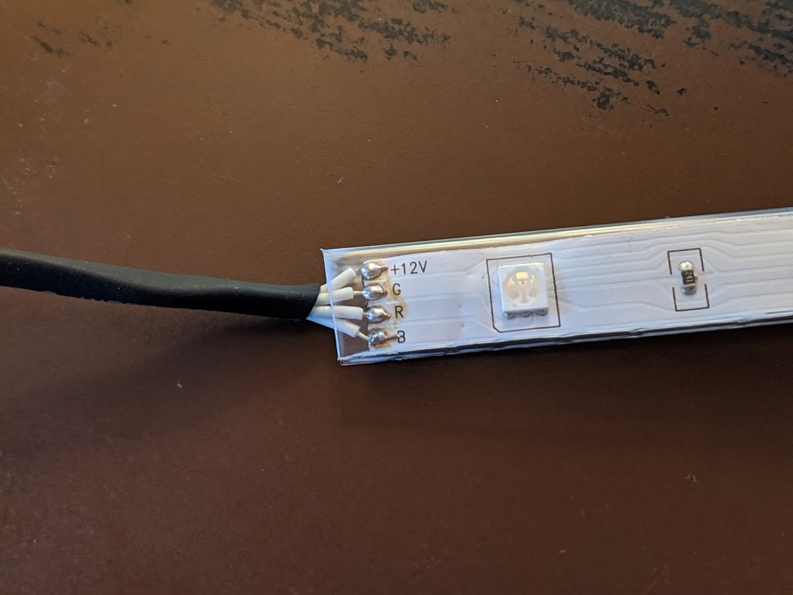
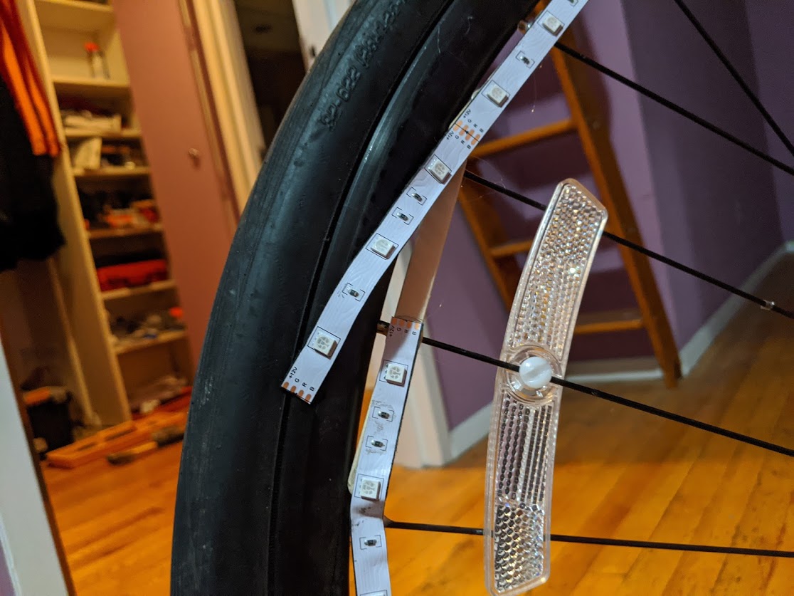
The lights are just segments of RGB LED strips you can buy on Amazon.
The computers for the two wheels and the body control the electronics to adjust the LEDs (MOSFETs acting as low-side switch).
The whole pattern scheme is designed around:
- Different quantities of Red, Green, and Blue, combined together give a specific color
- I want to transition, smoothly, between many colors
- So come up with a pattern you can follow that does that, and has a definite sequence to follow to generate them
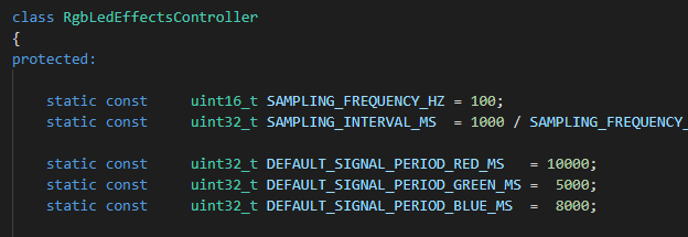
The pattern that gets followed is:
- Fade in/out the red, say, over 10 seconds.
- Then fade in/out the blue, say, over 8 seconds.
- Same with green.
- Calculate, at a given time, how much red, green, and blue to use
- Electrically cause that to happen (PWM on the MOSFETs)
Here is a graph of a simulation of those colors mixing, over time. Notice the period of red is constant, same with green and blue. They just intersect at different points.
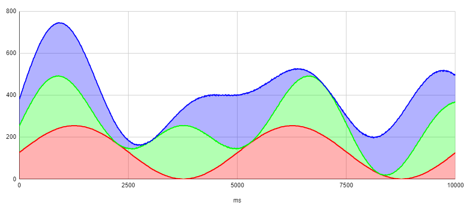
100 times each second, the quantity of red, green, and blue are re-calculated and adjusted
The Conductor
The Conductor computer picks values for the duration for each R, G, B value and transmits it periodically.
The Conductor actually follows the pattern itself, and sends along the exact internal state of its pattern, not just the pattern details, periodically.
This way, the receivers can make sure they have the right pattern parameters, as well as the specific point along that pattern generation to be at.
Power
The LEDs are run on 12V. The computers are run on 3.3v, which is created by stepping down the same 12V rail the LEDs use.
There are 3 zones on the bike that are powered independently:
- Front Tire
- Bike Frame
- Rear Tire
The bike frame has a pouch under the seat holding the battery pack, conductor, and bike frame computer.
Wires lead from there all along the body of the bike.
The wheels have the same configuration as each other.
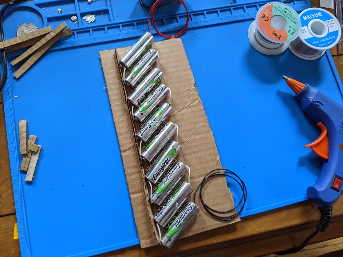
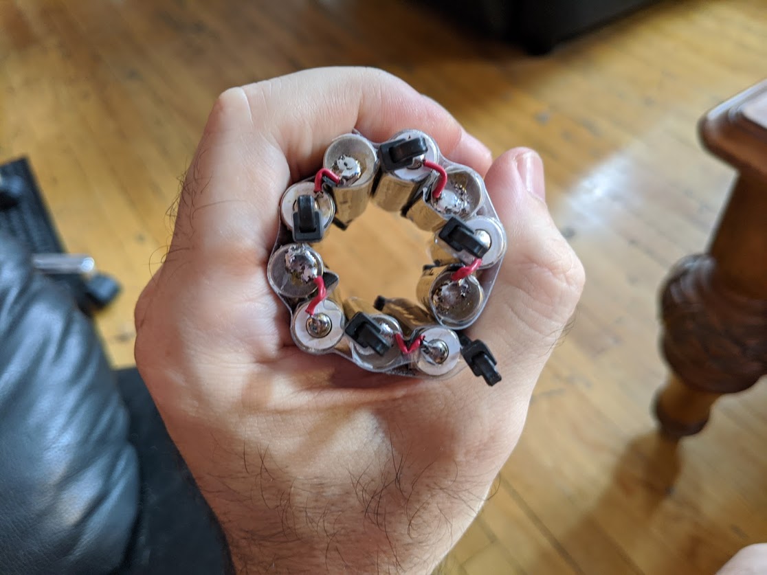
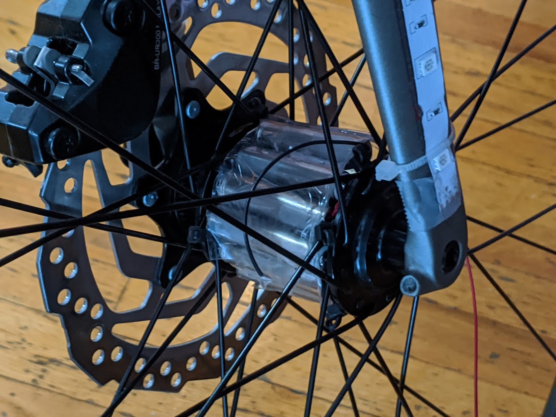
Each wheel has a computer, and a custom battery pack wrapped around the axle which powers the computer and lights.
Ignore the glue gun, these rechargeable NiMH batteries were soldered in series to create 12V (10 x 1.2v). Then wrapped in clear flexible tape.
Mounting
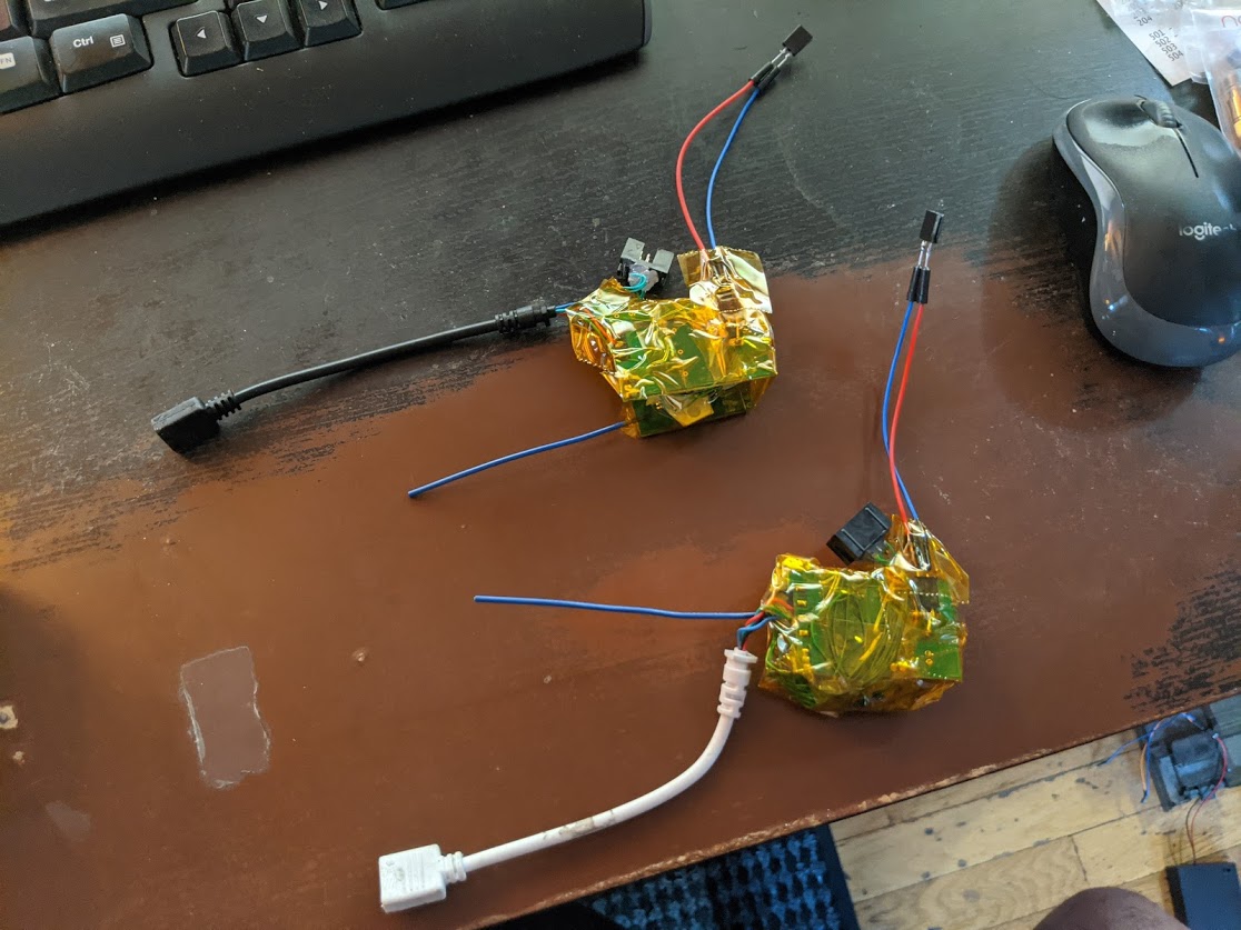
Tire Computers
Each has a computer, consisting of Arduino Pro Mini, radio transceiver, mosfets, regulator, and LED interface, all kapton taped together and zip-tied to the spokes of the wheel.
Bike Frame LEDs
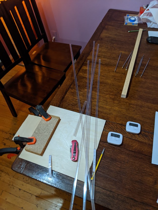
Don’t use zip-ties, they break the LED strips.
Instead, I housed them in strips of plastic to keep them rigid and protected against brushes with plants/people/objects/weather/etc.
I found 3M clear repar tape worked well to attach those strips to the bike.
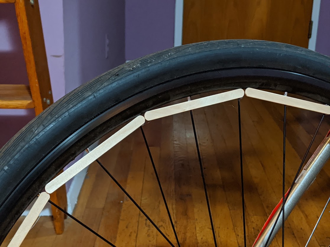
Wheel LEDs
Hot-glued popsicle sticks around the perimeter of the wheel area onto the spokes.
Then hot-glued the LEDs to the popsicle sticks.
Everything else I tried was a failure. This worked really well, though.
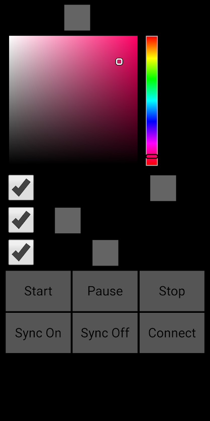
The Phone App and Bluetooth
The “app” is actually a webpage, running as an enhanced app within the phone, as exported by Chrome, on Android (should work on Apple, too).
Turns out javascript, through Chrome, can access to the Bluetooth Low Energy system on a phone and send arbitrary messages.
I programmed the Conductor computer to receive special serial messages, which the javascript sends, and the Bluetooth receiver feeding the Conductor relays.
With that I can decide specific colors to use always, or whether a pattern is being applied, brightness, etc..
I can also soft on/off the whole system.
Here is the interface presented by the webpage. I just have an old phone strapped to my handlebars showing this when I ride around.
No wifi or internet required. It’s using local BLE, which is always with me as I ride.
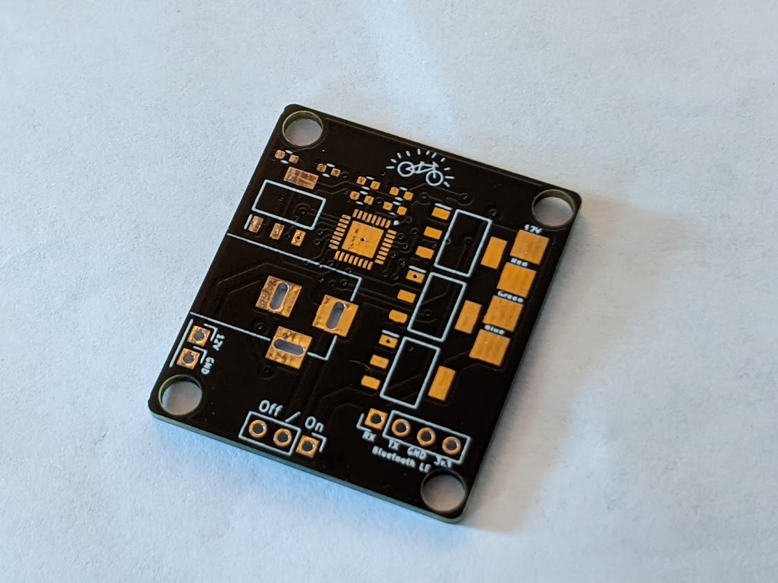
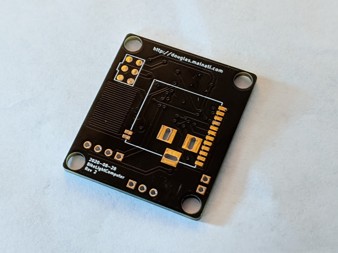
What’s next – PCB
I made up a prototype integrated PCB to do all the functions of the kapton-taped solution. In progress!
Code and Design
Github Conductor/Reciever code: (link)
Github WebApp code: (link)
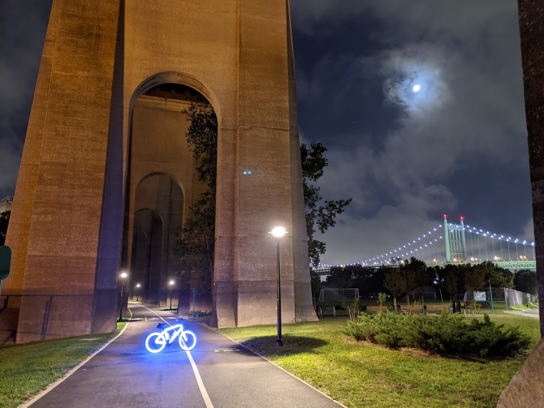
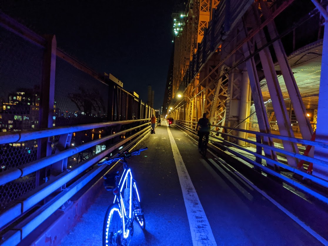
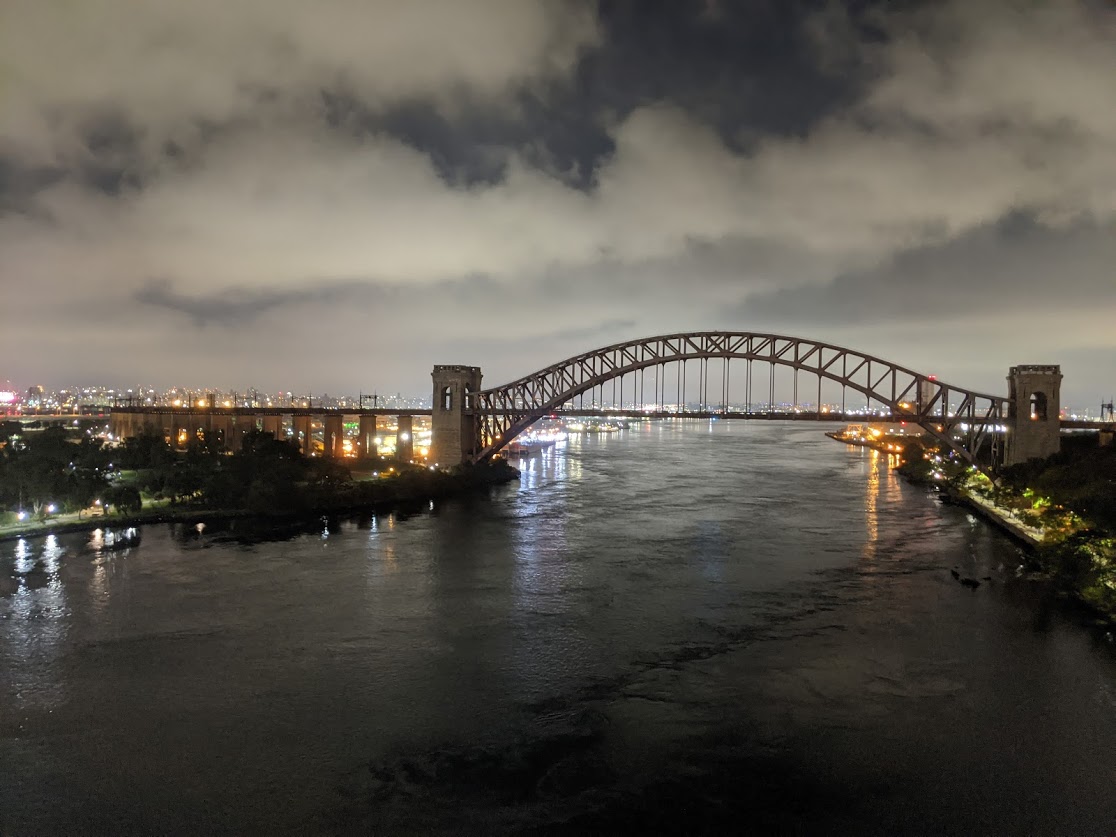
Some Nice Photos Out Biking
Since making the bike it’s been fun to ride around at night, which is something I never really did before.
Here are a few nice scenes I captured while out.